
One of the projects I had wanted to do on the trailer as we were planning to make our big run out west was to upgrade a number of electrical components on the rig. Primarily, I wanted to be able to run more of the AC system off battery power when we aren't hooked to shore power.
Excursus: Trailer Power
For some of our followers, you may not know (or care) how RV power works. Most rigs run two systems: DC and AC. AC is the same power most homes run (electrical outlets, lights, etc.) DC is a lower voltage system, often run off the big batteries like what starts your car. The DC system in our rig powers the LED lights, the audio system, and a handful of other items. If we want to run normal consumer electronics from the outlets, the fridges, the AC, etc., we need AC power. The AC system only works when we're connected to a 30A land line (known as "shore power"). We also have a 3000+ watt generator capable of providing enough power to run most of the things in our rig when we are camping without dedicated electricity.
The Upgrade
Now this is all fine and good until you want to fire up the coffee pot, the internet, or charge our devices without cranking up the generator. Up until today, there was no way to run those things off the battery, even though we had upgraded our battery to a 100Ah 12v lithium battery before departing. We could only run the DC circuits. My project has been to change that. Why? Because most campgrounds have quiet hours meaning we can't run a generator 24/7 (nor would we want to). It can also be a pain to fire up a generator just to make a pot of coffee in the morning.
The solution is what's known as an inverter. And inverter almost does the reverse of what an RV battery converter/charger does. The charger takes AC shore power and converts it into DC power to run DC circuits and charge the DC battery. An inverter, takes DC power (in this case, from a 12v DC battery) and outputs AC power. My project has been to introduce this inverter into our electrical system.
The Install
Here is my working diagram which got me from zero to completed project. It's a hand drawn mess, but maybe it'll help as I show other details.
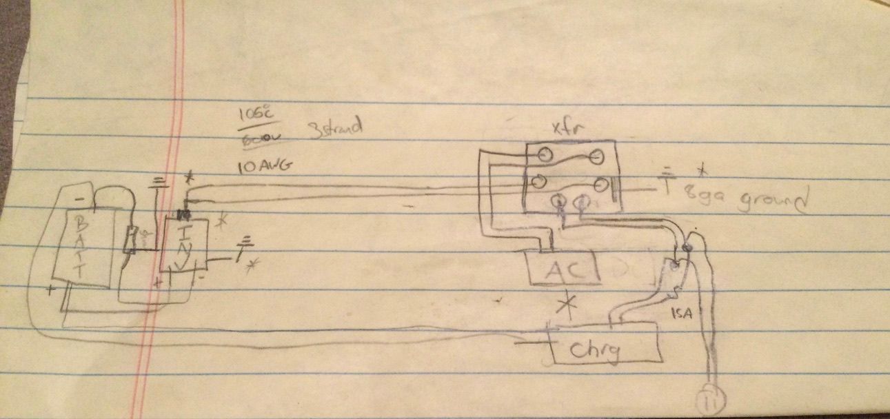
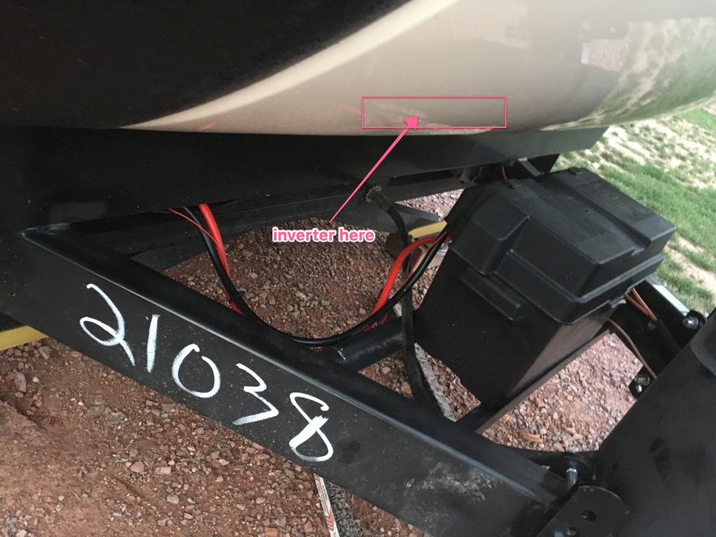
On the left side, we have our big ole battery. Below, you can see the thing where it sits just behind the propane tanks on the hitch. This battery already ran all the DC circuits and received charge from our existing charger (which also needed an upgrade due to the increased requirements of the Li battery). We are introducing the inverter into the system (the second box from the left). The inverter takes power directly from the battery. The specs require it sits pretty close to the battery to reduce voltage drop over the cables. So my inverter sits just inside the cargo bay behind the battery
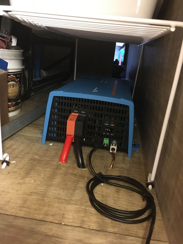
Here's a picture inside the cargo bay. I'm using a Victron Phoenix 12V/1200VA which means I can run up to 1200 volts of AC power on this guy. The way the math runs out, our single battery can only run 1200V for about an hour before it would go flat, but our usage shouldn't push it that hard. We won't be running the air conditioner or an instant pot on it, but it'll charge electronics, power the internet, or make coffee.
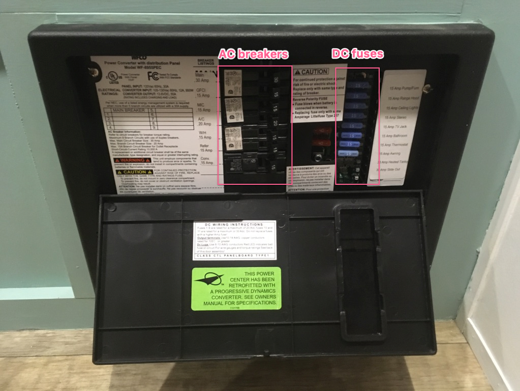
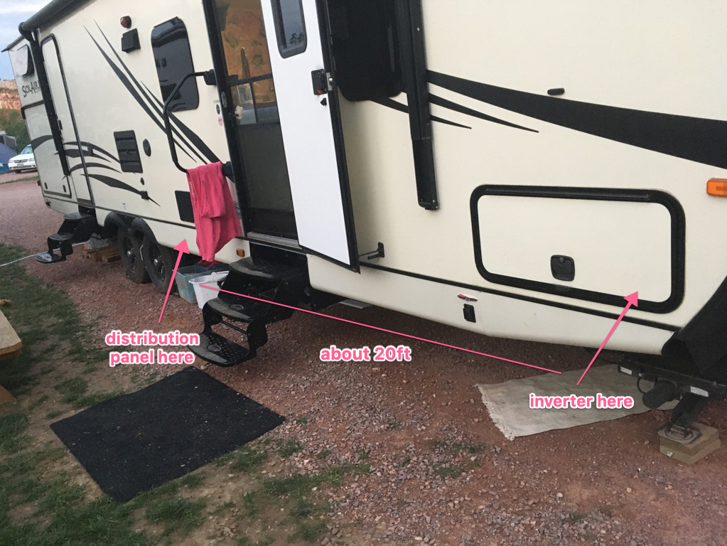
With this installed in the bay, we have to run the AC output all the way back to about the middle of the rig where the distribution panel sits. The distribution panel is what all the other electronics (lights, fridge, stereo, etc.) wire to in order to receive power. In a house, you have your breaker box which does the same thing. An RV has one, but it is usually split into the two power systems: DC and AC.
The AC side of the system can now receive power from two sources: shore power (when we plug in at a campsite or run the generator) and our battery. This creates a bit of a problem on its face because of the way the battery charges. The converter/charger mentioned earlier receives AC power (when connected) and converts it to DC power in order to charge the battery (among other things). This charger runs off the AC side of the system. When running of shore power, no problem! However, when the new inverter is powering the AC panel off the battery, it would be a bad idea to leave the converter running because it would attempt to charge the battery using the battery! Given losses across the system, this loop would deplete the battery fairly quickly without any benefit, perhaps even setting things on fire...
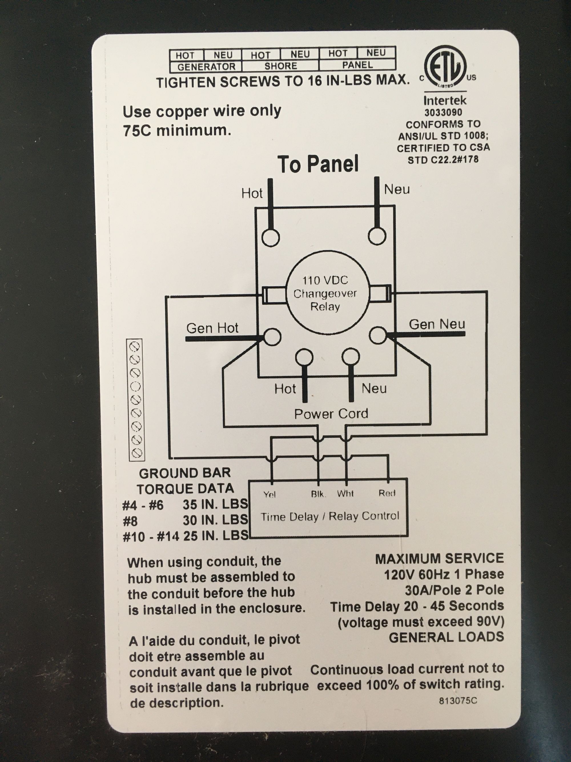
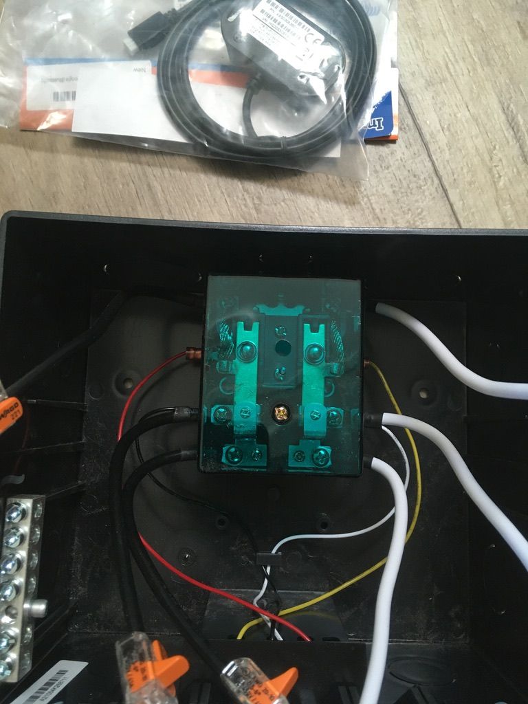
How to fix? The box in the upper right side of the diagram above is a transfer switch (labeled xfr). The transfer switch takes two input power sources and selects between whichever one is prioritized. In my system, if the shore power is present, it will prioritize that. However, if shore power fails or we unplug, it will switch over to the inverter. The charger is then switched to use the primary shore power line only instead of being wired to the AC distribution panel. This way, it only tries to charge the battery if shore power comes in. The converter portion will still run off the transfer switch output, thus running the DC system on whichever power source is present.
The Result
After about two days of wrestling with all the pieces and coordinating where to run wire, the system is (mostly) in. And it works great! We are currently sitting at a campsite so the shore power is running, but the new converter is charging our battery 100% now and the inverter will kick in automatically whenever I switch shore power off.
Success!
I say "mostly" because I have yet to wire the converter direct to shore power. It's hard to find parts in the small towns of South Dakota, and I need a 15A inline AC fuse before I wire the converter direct to the shore power. The distribution panel has a 15A breaker which handles the circuit protection for now, so until I find parts, I just need to cut the converter off manually using the breaker until I can find or order a fuse holder.
Only mistake which occurred under careful observation (so it didn't get to the point of causing damage) is I wired the new converter in reverse when I replaced the DC fuse panel. Bad news bears: it got close to melting some wire insulation and blew out two 30A protection fuses. I got it all wired and couldn't figure out why the battery was not charging. Quick check of the fuses showed they did their job and blew out when the reverse polarity kicked in.
Ultimately not a difficult project, just a lot of planning, a lot of learning about RV electrical systems and wire gauges. If anyone here reading this is an actual electrician and has any feedback, I would love to hear your take on this and to discuss anything I might have missed or not considered. I've spent hours lurking in forums, watching YouTube and reading manuals to ensure I'm loading things to spec, but experienced eyes are worth a lot more than my amateur fumblings.
I know most won't care about this update, but it was a big project for me and it is worth documenting what I did for my own sake if I ever needed to return to all the details. This channel will shortly return to our regular travel programming. Thanks for reading!
Credits
I am heavily indebted to this "RV with Tito" video which explained essentially what I wanted to do. I think I watched it three or four times...
The folks over at Battle Born Batteries gave me specs on what I needed to both charge our single lithium (also by Battle Born) battery and what inverter made sense to use with our (currently) single battery setup.
Comments